Majority adder implementation in Life rule B2/S2345

Abstract. We study Life-like cellular automaton rule B2/S2345. This automaton exhibits a chaotic behaviour yet capable for purposeful computation. The automaton implements Boolean gates via patterns which compete for the space when propagate in channels. Values of Boolean variables are encoded into two types of patterns — symmetric (False) and asymmetric (True). We construct basic logical gates and elementary arithmetical circuits by simulating logical signals using glider reactions taking place in the channels built of non-destructible still life. We design a binary adder of majority gates realised in rule B2/S2345.
We will exploit previous results on the constructions of feedback channels with still life patterns (previous studies since B2/S23456 and B2/S2345678), reducing the number of cells in state 1 on the evolution rule. Hence every pattern propagation is stimulated since a glider reaction that will produce a specific static geometric pattern, thus their interactions when they compete shall yield a binary value representation. Finally we design specific initial configurations to get implementations of universal logic gates and a binary adder based on majority gates inside B2/S2345.
Life rule B2/S2345
Dynamics of Life rule B2/S2345 is described for the next conditions. Each cell takes two states ‘0’ (‘dead’) and ‘1’ (‘alive’), and updates its state depending on its eight closest neighbours (Moore neighbourhood):
-
(a)Birth: a central cell in state 0 at time step t takes state 1 at time step t + 1 if it has exactly two neighbours in state 1.
-
(b)Survival: a central cell in state 1 at time t remains in the state 1 at time t + 1 if it has two, three, four or five live neighbours.
-
(c)Death: all other local situations.
Once a resting lattice is perturbed in B2/S2345 (few cells are assigned live states), patterns of states 1 emerge, grow and propagate on the lattice quickly. The main characteristic is that gliders and oscillators emerge but they do not survive for long time.
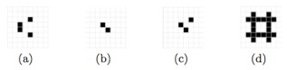
Fig. 1 Basic periodic structures in B2/S2345: (a) glider, (b) oscillator (flip-flop), (c) oscillator (blinker), and (d) still life configuration.
A set of minimal particles, or basic periodic structures, in rule B2/S2345 include one glider (period one), two oscillators (one blinker and one flip-flop, period two), and finally one still life configuration (see Fig. 1). The still life pattern in B2/S2345 has a relevant characteristic. They are not affected by their environment however they do affect their environment). Therefore the still life patterns can be used to build channels, or wires, for signal propagation.
Computing by competing patterns
The easiest way to control patterns propagating in a non-linear medium circuits is to constrain them geometrically. Constraining the media geometrically is a common technique used when designing computational schemes in spatially extended non-linear media. For example ‘strips’ or ‘channels’ are constructed within the medium (e.g. excitable medium) and connected together, typically using arrangements such as T-junctions. Fronts of propagating phase (excitation) or diffusive waves represent signals, or values of logical variables. When fronts interact at the junctions some fronts annihilate or new fronts emerge. The propagation in the output channels represent results of the computation. Hence we built a computing scheme from channels — long areas of ‘0’-state cells walled by still life blocks, and T-junctions (T-junction based control signals were suggested also in von Neumann works, and used by Banks and Codd as well.) — sites where two or more channels join together.
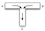
Fig. 2 T-shaped system processing information.
Each T-junction consists of two horizontal channels A and B (shoulders), acting as inputs, and a vertical channel, C, assigned as an output (see. Fig. 2).
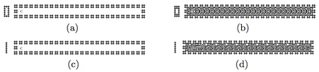
Fig. 3 Feedback channels constructed with still life patterns ((a) and (c)) show the initial state with the empty channel and one glider respectively. The symmetric pattern represent value 0 (b), and non-symmetric pattern represent value 1 (d) late of glider reaction.
Boolean values are represented by position of gliders, positioned initially in the middle of channel, value 0 (Fig. 3a), or slightly offset, value 1 (Fig. 3c). The initial positions of the gliders determine outcomes of their reaction. Glider, corresponding to the value 0 is transformed to a regular symmetric pattern, similar to frozen waves of excitation activity (Fig. 3b). Glider, representing signal value 1, is transformed to transversally asymmetric patterns (Fig. 3d). Both patterns propagate inside the channel with constant, advancing unit of channel length per step of discrete time.
Implementation of logic gates and beyond
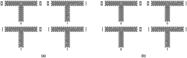
Fig. 4 Implementations of or and and gates at the Life rule B2/S2345. Input binary values A and B they are represented as ‘In/0’ or ‘In/1,’ output result C is represented by ‘Out/0’ or ‘Out/1.’ Thus (a) display OR gate, and (b) AND gate implementation.
Figure 4a shows a way to implement an OR gate. Due to different locations of gliders in initial configurations of gates, patterns in both implementations of gates are different however, results of computation are the same. Similarity a codification to implement AND gate is shown in Fig. 4b.
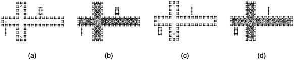
Fig. 5 NOT gate implementation for input ‘1’ (a,b) and input ‘0’ (c,d). This way (a) and (c) display initial configurations, (b) and (d) display final configurations.
The NOT gate is implemented using additional channel (as a trick), where control pattern is generated, propagate and interfere with data-signal pattern. Initial and final configurations of NOT gate are shown in Fig. 5. A consequence with this idea is that the number of control channels growth proportionally to number of gates in the circuit. Of course, we accept that it could not be the most elegant and efficient way of constructing NOT gate, but useful for our purposes at the moment.
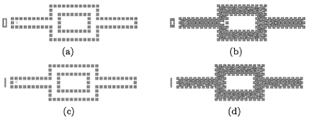
Fig. 6 Configurations of delay element for signal ‘0’ (a) and (b), and signal ‘1’ (c) and (d). Thus (a) and (c) shows initial configurations, (b) and (d) final states.
On the way we can design a delay element as shown in Fig. 6. Useful to delay signals (wave propagations) and synchronize multiple collisions.
Majority gate implementation on three input values can be represented as a logical proposition: (a ∧ b) ∨ (a ∧ c) ∨ (b ∧ c), where the result is precisely the most frequently value on such variables [Minsky, 1967]. Implementation of majority gate in B2/S2345 is shown in Fig. 7. The gate has three inputs: North, West and South channels, and one output: East channel. Three propagating pattern, which represent inputs, collide at the cross-junction
of the gate. The resultant pattern is recorded at the output channel.
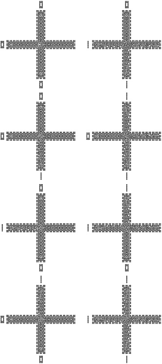
Fig. 7 Final configurations of the MAJORITY gate. Majority input values In/0 (first column), and majority input values In/1 (second column).
NOT-MAJORITY binary full adder
Here we will implement a binary adder constructed of three NOT-MAJORITY gates and two inverters. Such type of adder appears in several publications, particularly in construction of the arithmetical circuits in quantum-dot cellular automata. Original version of the adder using NOT-MAJORITY gates was suggested by Minsky in his designs of artificial neural networks.
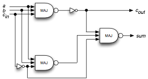
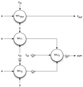
Fig. 8 Circuit and schematic diagram respectively of a full binary adder comprised of NOT-MAJORITY gates. Delay elements are not shown.
Figure 8 shows the classic circuit illustrating the dynamics of this adder. Right diagram (Fig. 8) represents a scheme of the adder to implement in B2/S 2345. The scheme highlights critical points where some extra gates/wires are necessary to adjust inputs and synchronize times of collisions.
Fig. 9 Movie simulating inputs a=1, b=0, c=0.
Finally this adder is implemented on 1,402 × 662 lattice that relates an square of 928,124 cells lattice with an initial population of 56,759 cells in state ‘1.’ Final configurations of the adder for every initial configuration of inputs are shown in our full paper, with a final population of 129,923 alive cells on an average of 1,439 generations.
Implementations and constructions were are done with Golly system. RLE files to reproduce the binary adder with the CA B2/S2345 for all binary inputs.

Contributions by Kenichi Morita, Andrew Adamatzky, and Maurice Margenstern.
Paper: Majority adder implementation by competing patterns in Life-like rule B2/S2345 [PDF]
Journal: Lecture Notes in Computer Science 6079, 93-104, 2010.
Instituto de Ciencias Nucleares, Universidad Nacional Autónoma de México, México.
University of the West of England, Bristol, United Kingdom.
9th International Conference on Unconventional Computation 2010, University of Tokyo, Tokyo, Japan, June 21-25, 2010.
Supported by Engineering and Physical Sciences Research Council (EPSRC), United Kingdom, grant EP/F054343; DGAPA UNAM, and Grant-in-Aid for Scientific Research (C) No. 21500015 from JSPS.
